You have a bunch of unlabelled drives that were removed from a server. There is no documentation. You have no idea where to start. Welcome to RAID forensics! This article explains the most common mistakes investigators make and how to avoid them without compromising evidence integrity.
The “Pull and Pray”
The standard field approach – pull the drives, image them individually, rebuild the RAID in software. Sounds methodical. In practice, it’s a technical minefield. As one investigator put it bluntly:
“I have just imaged 4X4TB disks… I cannot rebuild the RAID ….despite having tried all the combinations.”
The frustration is understandable. Without a documented configuration, you have no evidence. It’s like navigating using a map where half the roads are missing.
“If you don’t have the config you can manually recover this info by finding the start of the $MFT and mapping it across the drives (you can use other files but the $MFT has a known structure and numbered records which make life (relatively) easier.”
In a Windows-based RAID, the MFT (Master File Table) acts as the North Star. Since MFT records have a fixed size and are sequentially numbered, you can track how they jump from one drive to another to “calculate” the stripe size and drive order. It is a clever forensic shortcut, but it still requires parsing raw hex data – a tedious and time-consuming task. Another user illustrates this precisely:
“I have an Acer Predator Trion 500 laptop with two PCIe (NVME) drives setup as a RAID0. I’m now trying to figure out the stripe size of the raid but fumbling in the dark…”
The phrase “fumbling in the dark” is exactly what happens when there are no configuration details. Here is why that happens.
The physical order of the drives is rarely the same as the logical order used by the controller. With a 4-drive array, there are 24 possible ordered combinations. With 9 drives, that jumps to 362,880 variants.
And drive order is only one configuration parameter. Other factors such as stripe size, parity, RAID type, and offset, multiply the number of possible combinations even further, making RAID reconstruction a much larger combinatorial problem.
In most RAID configurations, data isn’t written linearly. It’s chopped into chunks called stripes. The stripe size could be 64 KB, 128 KB, 1MB, or even 512B. If you guess wrong, the file structures won’t align, and every file larger than one stripe will be corrupted.
RAID controllers don’t always start writing data at the very first sector of a disk (Sector 0). They often leave a reserved area for metadata or proprietary boot code. If Drive A starts at Sector 0, but Drive B starts at Sector 2048, and you treat them as starting at the same point, the data stripes will be “skewed”. This will make the file system unreadable.
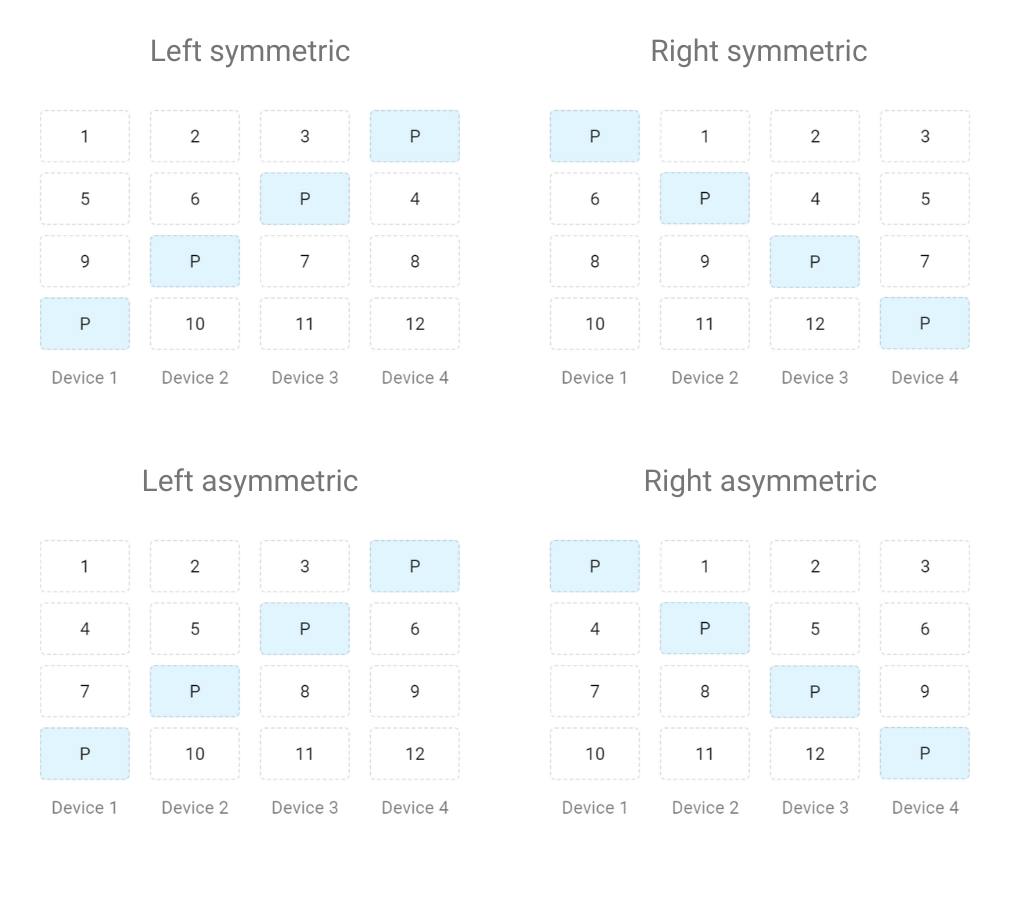
In RAID 5 or 6, parity (the redundancy data) rotates across drives in a specific pattern (Left symmetric, Right symmetric, etc.). If you don’t know the rotation pattern, you can’t distinguish between actual data and the parity bits.
One Image File Does Not Tell the Whole Story
There’s a misconception that confuses even experienced practitioners: treating a single drive image as a complete dataset. A real-world example from a community forum illustrates this exactly.
The question: “I am trying to parse out image copies from a Linux server, likely amazon EC2. The local main drives which were on a RAID configuration were pulled and then imaged. When I use FTK the filesystem is unrecognizable… I have a feeling the image is corrupt.”
The answer: “If there was a RAID, I assume there should be more than one image (unless it was RAID 1) and you have to use software to reconstruct the RAID before reading the data.”
Automating the Reconstruction
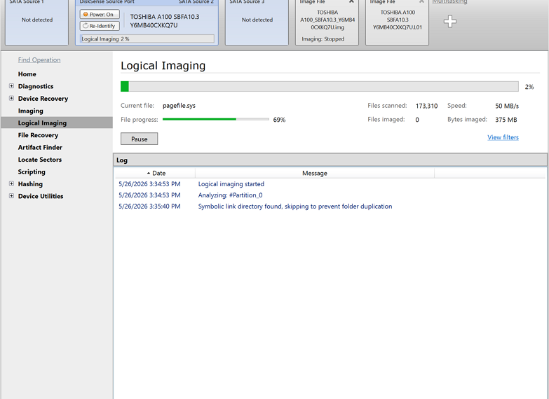
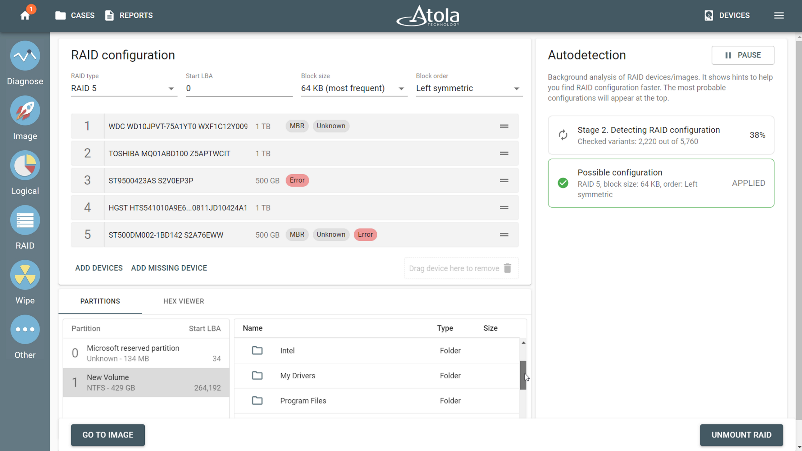
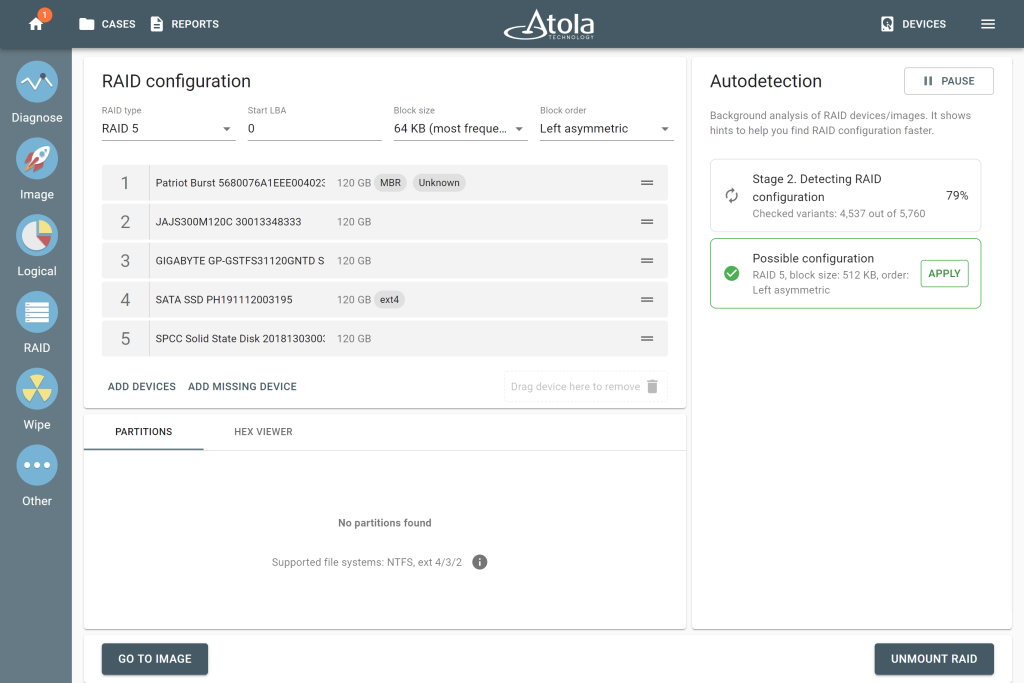
When there is no documentation and it is not possible to do a manual analysis, tools that can automatically put RAID together can make a big difference. Atola’s TaskForce 2, for instance, includes a RAID autodetection module that uses heuristic algorithms to identify RAID type, start LBA, block order, and stripe size – evaluating up to 200,000,000 combinations in minutes across RAID 0, 1, 5, 6, 10, and JBOD configurations. Simply select the source drives or image files, wait for the configuration suggestion, and click Apply. TaskForce 2 presents the reconstructed array as browsable files and folders, allowing imaging of the entire RAID.
The Proprietary Wall
Not all RAIDs are the same, and this is very clear in the world of Network Attached Storage. It’s a storage solution usually built around one or more hard drives arranged in a RAID configuration to protect against data loss. Synology is among the most popular NAS manufacturers. It is known for its user-friendly interface and robust performance, but from a forensic standpoint, it is one of the more challenging platforms to work with.
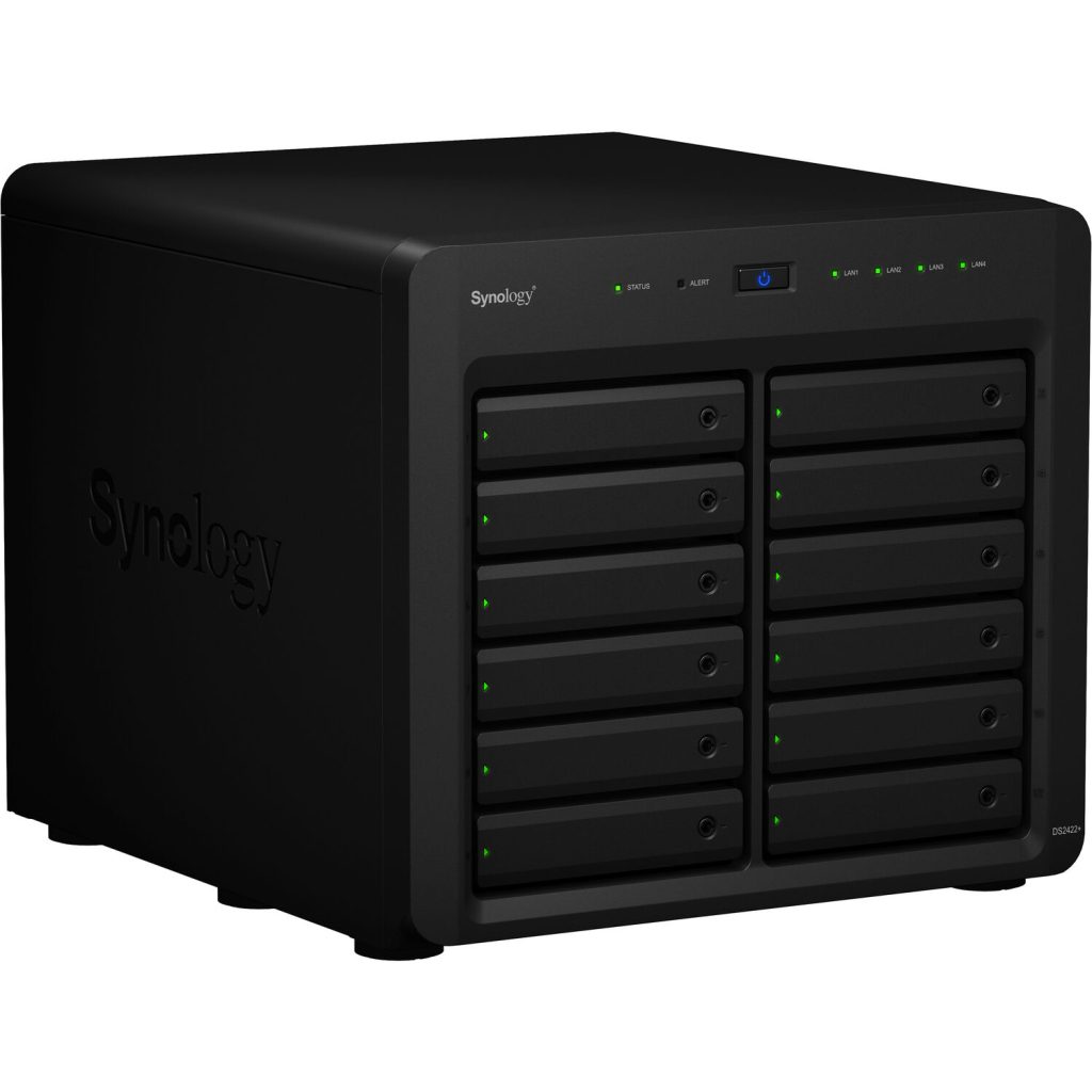
The reason is simple: Synology NAS systems don’t just run standard RAID levels. They layer proprietary implementations on top – and that’s where investigations get stuck. The DFIR field questions speak for themselves.
“Have a 4 drive Synology that is a dead box. Looking for suggestions on what is best to get an image since it’s raided. TIA”. Or a more technically specific scenario: “Has someone experienced rebuilding a Synology RAID 5 with read-write ssd cache within Linux in order to mount the volumes (btrfs)?” Both questions point to the same wall. Standard reconstruction workflows weren’t built with Synology’s architecture in mind.
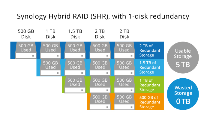
This proprietary RAID is called SHR (Synology Hybrid RAID). It offers 1-disk redundancy (SHR), or 2 (SHR2). Standard RAIDs have a well-known limitation with mixed-capacity drives: the smallest drive is a bottleneck for other drives. In an array of 500 GB, 1 TB, 1.5 TB, and 2 TB drives, every drive contributes only 500 GB of space. SHR uses all available capacity and for the end user it looks like a single unified volume, but under the hood it’s several RAID 1, 5, or 6 joined together.
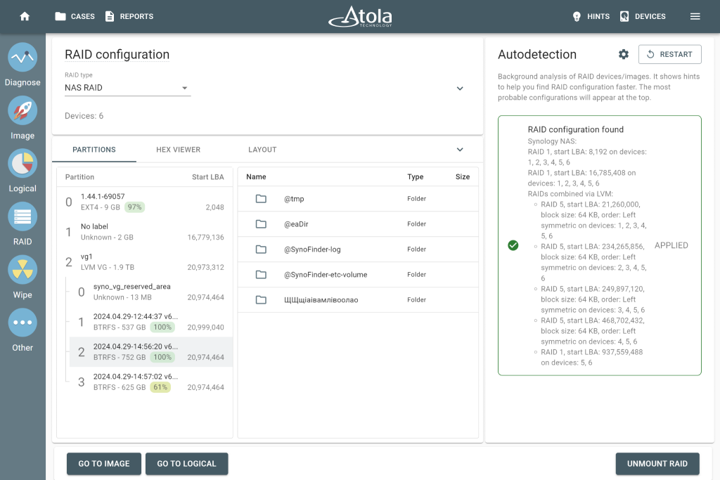
For Synology specifically, Atola TaskForce 2 closes the gap. It supports both SHR and SHR2 RAID types. Its RAID module detects the array configuration automatically, and shows the result as browsable partitions, folders, and files. No manual reassembly, no need to guess proprietary block logic.
Missing Piece, Full Picture
“Anyone have experience forensic imaging an American Dynamics NVR, configured in RAID 5… the filesystem is unrecognizable… I have a feeling the image is corrupt.”
So, when a drive or image file is damaged or lost, it doesn’t automatically mean the data is gone. Think of RAID 5 or 6 like a puzzle, where the box contains spare pieces. If you lose one or two pieces, you can still figure out what the rest looks like. That’s essentially what parity does. It stores just enough extra data across all the drives so that if one goes missing, the array can do the math and fill in the gap.
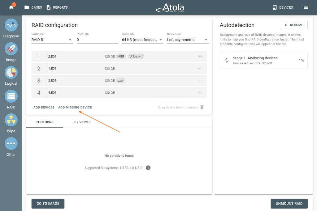
With the right tool, that piece can be reconstructed automatically. In Atola TaskForce 2, if one drive is lost or too damaged to use, select the available members and click the Add Missing Device button. TaskForce 2 works out the rest using the redundancy already built into the array, and produces a complete image after all.
The same applies when drives are present but struggling. If TaskForce 2 hits errors while scanning, it identifies the affected drive and keeps processing. The partitions can still be browsed and imaged.

Mantra: Protect the Source
Most RAID errors occur in the technical nuances. But, this one happens before you even get there. Some investigators, under time pressure or without the right equipment, choose to work directly with a live system – booting the NAS, accessing it through the manufacturer’s interface, or connecting via SSH. It’s faster. It’s familiar… And it can silently destroy a case.
The risk was spelled out clearly in the Digital Forensics Discord community exchange about a QNAP device:
“Depends on how strict you want your process to be, and what evidence you might be stomping on by booting it, running all the QNAP UI services, and accessing via SSH. First approach is entirely defensible if you have the storage capacity, tools, and time. If you don’t, then prepare to defend yourself about why data on the exhibit was modified while in custody.”
One response hits the nail on the head:
‘Mantra: Protect the source.’
The moment you boot a live system, data changes. Timestamps update. None of that is malicious, but all of it is modification, and in a courtroom, modification requires explanation. The question from opposing counsel won’t be technical. It will be simple: “Why did the evidence change after it was seized?” That’s a difficult question to answer well without documented, defensible methodology behind you.
This forensic approach eliminates problems before they start. Atola TaskForce 2 is, first and foremost, a forensic imager. It provides hardware-level write protection from the moment a drive is connected, ensuring that the source is never altered during acquisition. Every action is logged, every step of the process is documented, and the final report provides full transparency of what happened and when. The data you image is the data that was there – and you can prove it.
In digital forensics, that provability isn’t a detail. That’s the whole point.