Deepfakes are becoming increasingly sophisticated, making their detection more challenging every day.
Although several tools have been developed to identify the inherent traces left by synthetic generation methods, scientific research shows that multiple factors can significantly reduce their effectiveness in real-world scenarios. For example, when a synthetic-generated image is shared on a social media platform, its metadata and container traces are stripped away. In addition, the platform typically resizes and compresses the image, potentially undermining many techniques that rely on subtle pixel-level clues.
This is where the Amped Authenticate Perspective filter proves valuable for assessing the authenticity of a digital image. Synthetic generation methods still struggle to produce geometrically consistent elements, such as accurate shadows. These features tend to remain stable even after various processing steps, making them useful in many practical situations. For instance, if you print and then re-photograph a deepfake, you create a new file that can bypass all metadata and container checks. Nevertheless, its visual content is still inauthentic.
The Perspective filter analyzes the consistency of geometric features in an image. More specifically, a forensic practitioner can verify whether one or more vanishing points are consistent and align correctly on the same horizon.
In the following section, we outline a step-by-step procedure for applying the filter to a digital image.
Vanishing Points in a Nutshell
Before proceeding, it is useful to recall a fundamental geometric concept: perspective.
A vanishing point in an image is the location where parallel lines in the real world appear to converge, either within or beyond the frame, as they extend into the distance. A common example is a straight road or a long hallway: the edges seem to meet at a single distant point, which is the vanishing point.
Most real-world scenes contain one or multiple vanishing points, depending on the orientation and arrangement of the objects in the space.
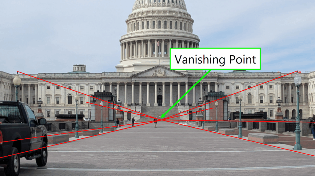
In the example below, lines that are parallel in the real world (highlighted in red) converge toward a vanishing point within the digital image.
Note that images can contain multiple vanishing points. Indeed, each direction in the 3D world corresponds to a vanishing point in the image, as shown in the example below.

Closely related to the concept of the vanishing point is the horizon line. This is the line on which all vanishing points corresponding to directions along the ground plane lie. In other words, it represents the viewer’s eye level within the scene and serves as a reference for assessing geometric consistency. In the following example, the horizon line is illustrated as the locus of all vanishing points associated with ground-level directions.

A fundamental rule of perspective is that all lines lying on the ground plane, as well as on any other planes parallel to it, share the same horizon line. This principle is particularly valuable when analyzing images of environments such as rooms, urban landscapes, or architectural scenes, where the floor is typically flat. In such cases, objects and structures rest on the ground, creating multiple sets of parallel planes. These planes, in turn, generate vanishing points that align along a common horizon line, as illustrated in the example below.

In the example above, one might initially argue that the two lower red lines rest on a surface perpendicular to the floor rather than parallel to it. However, upon closer consideration, it becomes clear that these lines can be included in the analysis. This is because they are parallel in the real world and their direction lies on planes that are also parallel to the ground.
To summarise:
- For a given direction, parallel lines in the real world converge to a single vanishing point in the two-dimensional image.
- Vanishing points obtained from lines lying on planes parallel to the ground will all be located along the horizon line.
These principles apply under the assumption that no optical distortion is present in the image. If distortion is present, it must be corrected first. This can be accomplished using Amped FIVE’s Undistort, Correct Fisheye, or Camera Calibration filters. Detailed guidance on these tools is available on the Amped Blog.
With these foundational concepts established, a step-by-step description of the Perspective filter can be provided.
How the Perspective Filter Works
The Perspective filter can be found within the Geometrical Analysis category of Amped Authenticate. When updating from a previous version of the software, the filter may appear disabled during the initial run. The user can easily activate it as follows:
- Right-click on the filter and select Enable.
- Click Save Settings to overwrite the default loading configuration.
Once enabled, the filter will remain active in subsequent sessions, ensuring it is readily available for perspective analysis workflows.

The analysis process consists of two main stages:
- Identification of Vanishing Points – The forensic examiner selects up to five distinct vanishing points within the image by marking groups of lines that are expected to be parallel in the real world. Each group of lines should correspond to the vanishing point associated with one direction of the ground plane. If the parallel lines within a single group do not converge to a common vanishing point, the filter flags a geometrical inconsistency within the image.
- Verification of Horizon Line Consistency – If all selected vanishing points are mathematically consistent, the filter then checks for the existence of a horizon line intersecting all of them. As discussed earlier, this alignment is expected when all vanishing points are derived from lines lying on planes parallel to the ground. If no such line can be established, Amped Authenticate alerts the examiner that an anomaly is present in the image geometry.
Selecting Lines for a Vanishing Point
Each vanishing point is managed through its own dedicated tab in the right-hand panel of the interface. Similar to the Shadows and Reflections filters, the examiner can select wedges rather than simple lines. This approach can help reduce errors introduced by the limited resolution of the image, as wedges allow for a more accurate estimation of line directions and convergence points.

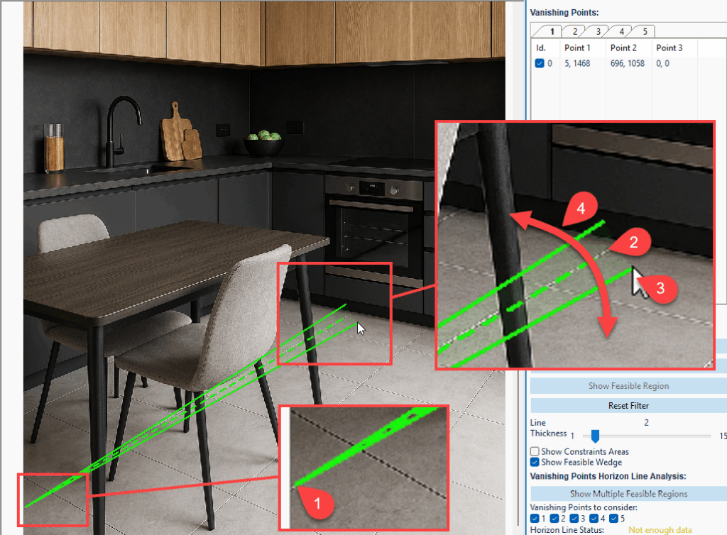
To begin, the examiner identifies a group of parallel lines and selects the first by left-clicking at one endpoint within the image. The second click is placed at the opposite endpoint, thereby defining the line’s direction. By moving the mouse, the wedge width can be adjusted to account for the uncertainty introduced by image resolution and quality.
A third left-click finalises the wedge selection, and a fourth click confirms and registers the list of constraints. The coordinates of the selected points are automatically recorded in the tab corresponding to the associated vanishing point. If necessary, an individual wedge can be removed by right-clicking on it.
The mouse wheel can be used to zoom in and out, enabling precise control over point selection. Similarly, image panning can be performed by holding the CTRL key while dragging the mouse across the image. These functions facilitate navigation and accuracy when drawing wedges.
The forensic examiner may continue adding lines, with the filter automatically searching for an intersection among the wedges. This intersection represents the vanishing point for the corresponding direction. The Current System State indicator will display System Feasible until a valid geometric intersection is identified.
Checking the Consistency of an Individual Vanishing Point
In our example, the floor tiles seem to have a consistent perspective, as indicated by the green text below the tab.

Such an intersection can be visualized by clicking on the dedicated button. A new window will appear showing the feasible region in yellow, as in the example below.

The described procedure can now be applied to other directions (up to 5).
In the example below, two additional directions are taken into consideration, illustrated by the pink and blue lines. While it may be uncertain whether the kitchen furniture is perfectly aligned with the floor tiles, it is reasonable to assume that they lie on a plane parallel to the floor. This assumption allows the addition of new lines in separate tabs corresponding to these directions.
As in previous cases, the use of wedges enables the identification of a feasible region—the area in which the vanishing point for that direction is located.


Checking the Consistency of Combined Vanishing Points
In the example shown, Amped Authenticate indicates that each individual tab successfully identifies a feasible region corresponding to a vanishing point. However, the Horizon Line Status reports that no single line intersects all of the feasible regions. In a genuine image, all vanishing points derived from planes parallel to the ground should align along the horizon line. This is not the case here, indicating a potential anomaly in the image’s geometry.
For enhanced visualization, the analyst can enable the Show Multiple Feasible Regions option, which displays all identified feasible regions simultaneously (see the example below). This view reveals that the vanishing point corresponding to the floor lies significantly below the others. In conclusion, the addition of the third vanishing point exposes a clear inconsistency in the image’s perspective, supporting the hypothesis of manipulation or synthetic generation.

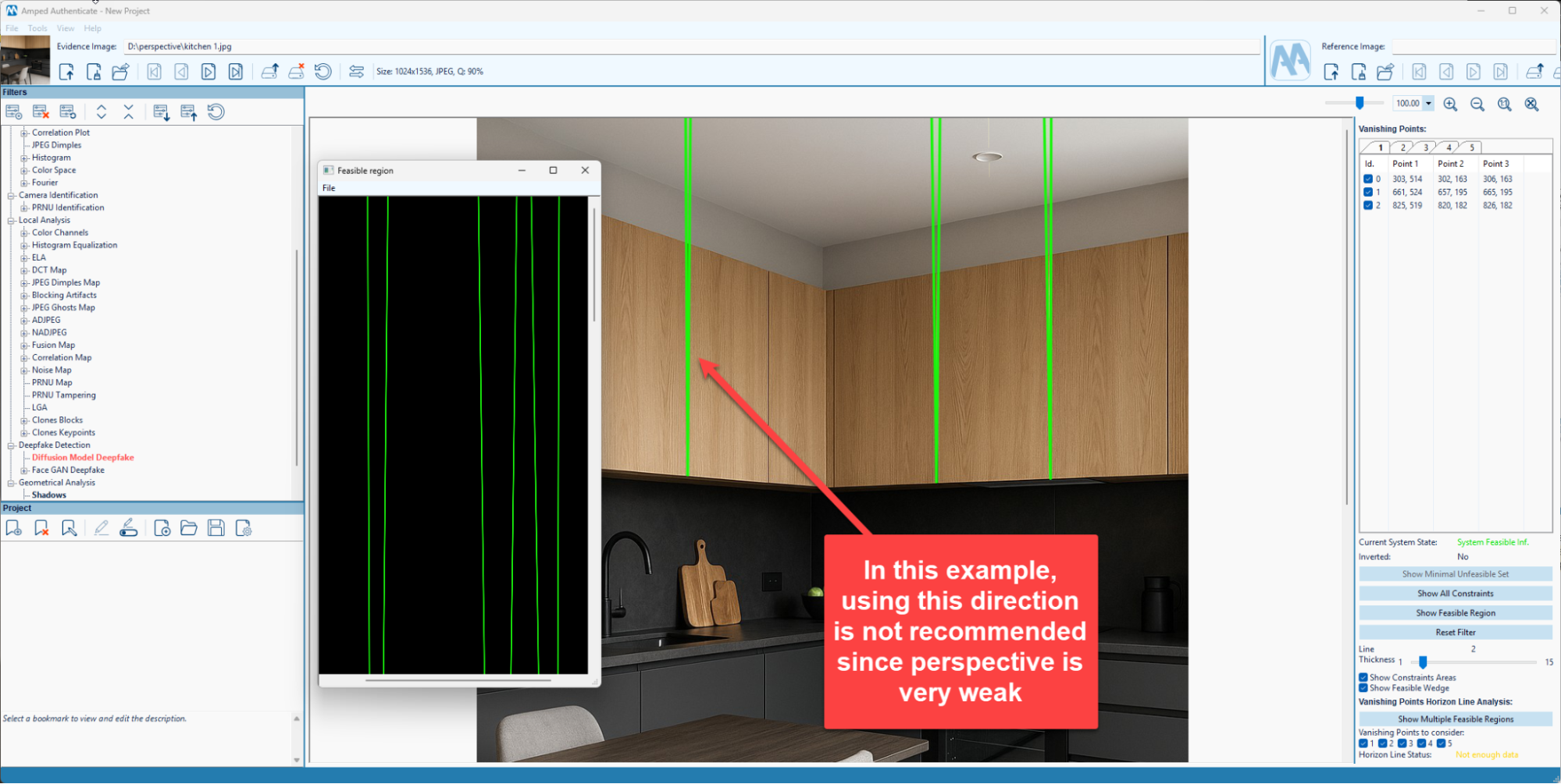
Tip: Check for Perspective Where There Is Perspective
Although the filter is highly practical, it is important to emphasise that lines exhibiting visible perspective should be prioritised when selecting directions for perspective analysis. These are lines that are not parallel in the two-dimensional image. Such lines contribute to reduced uncertainty in the localisation of the feasible region, thereby improving the precision and reliability of the vanishing point estimation.
Analyzing Perspective in Video Frames
Perspective analysis is not limited to still images; it can also be applied to video content.
The Authenticate Video Mode enables the examiner to select any frame from a video and seamlessly transfer it to the Image Mode for analysis with the Perspective filter. This can be achieved by pausing on the frame of interest and clicking the Send Frame to Image Mode button (see the image below).
Once the frame is transferred, the Image Mode opens, allowing the analyst to carry out the full perspective analysis using the same methodology described for still images.

Conclusion
In this article, we presented the new Amped Authenticate Perspective filter that can be used to spot perspective inconsistencies in synthetically generated images. More specifically, the forensic practitioner can verify whether one or more vanishing points are consistent and align correctly on the same horizon. This technique can be applied even when the image metadata/container is stripped away or compression operations have been applied by a social media sharing platform.
To see the new filter in action, check out the video below or visit the amped blog to read the latest Amped Authenticate release.