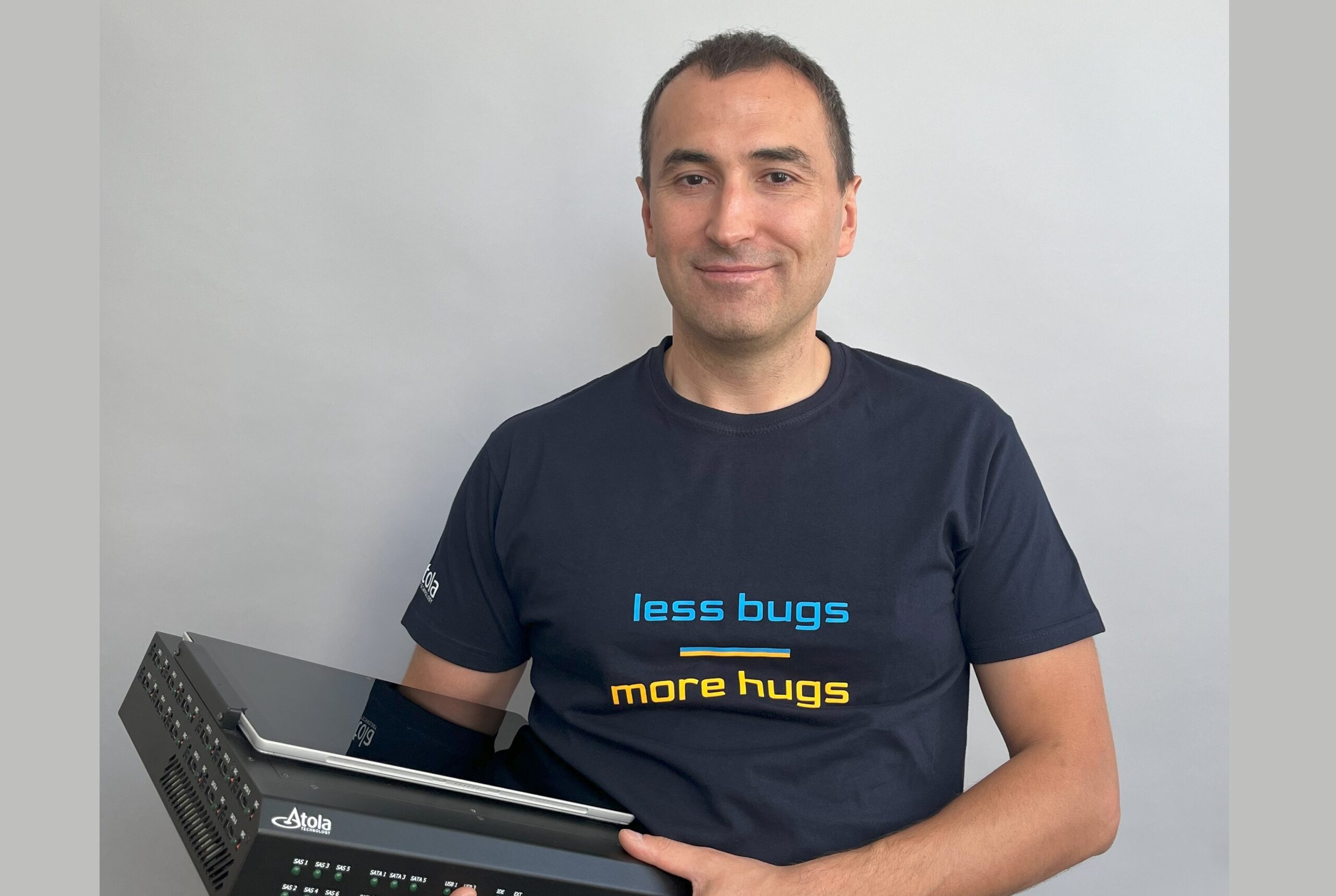
In this interview, we speak with Andrew Tyshchenko, the Head of Hardware at Atola Technology. With over 18 years at Atola, Andrew has led the design of all the company’s hardware products. Today, we discuss Atola’s latest release, the TaskForce 2 forensic imager, and explore the innovative solutions his team developed to make it a robust tool for forensic labs.
FF: Launched in July 2023, TaskForce 2 arrived exactly five years after the first-generation TaskForce. What challenges were you looking to address with the new imager?
We designed TaskForce 2 to meet the growing needs of digital forensic examiners. Our customers reported the increasing challenge of faster evidence processing due to the ever-growing number of drives involved in cases and their increasing sizes.
Each of our forensic devices has surpassed its predecessor in capabilities and complexity. TaskForce 2 is an evolution of the TaskForce architecture, featuring more processing power and additional ports for various types of connections.
To better understand the differences between these two imagers, it’s important to note that TaskForce was designed as a dual-purpose product: a compact yet powerful field unit, which can also be a stationary device for a forensic lab. Its physical dimensions were a key factor when choosing its computing platform, power consumption, and heat dissipation. TaskForce’s hardware was a balanced solution that met the requirements for both use cases.
With the development of TaskForce 2, we wanted to provide an even more powerful computing platform to empower our users with the capability to image 26 drives in parallel.
FF: How did your team choose the key components for TaskForce 2?
TaskForce 2 incorporates over 250 types of components, totaling more than 1,500 pieces. Let’s dive into a few of the key components.
To meet the demands of the features already implemented in TaskForce—like RAID autodetection and hash calculation, along with a significant increase in the number of ports—we required a powerful processor and motherboard. We started by selecting a Supermicro motherboard that supports 3rd Gen Intel Xeon scalable processors in the LGA-4189 socket.
Out of the whole range of supported CPUs, we chose a Xeon Silver 4309Y, with 8 cores, 16 threads, 12MB of cache, and a moderate 105W thermal output, ideal for handling parallel imaging streams. We also designed a custom cooling system using Dynatron N11 coolers and magnetic levitation fans and custom air ducts to keep the system cool while minimizing noise levels. Acoustic comfort is important to our customers, therefore we provide fan speed controls in software settings.
When the computing load is low, the user can keep the fans at a minimum speed and increase the speed when the computing load increases. For example, when many imaging sessions with hash calculation are running.
The chosen motherboard supported a variety of drive ports: SATA, NVMe PCIe 4.0, and USB 3.2. To meet the desired product specifications, all we lacked was the support of 8 SAS ports, which we supported using a PCIe add-on card.
TaskForce 2 includes 16GB DDR4 server-grade ECC RAM for error detection and correction. It also features an IcyDock four-slot drive bay for convenient M.2 and U.2 drive connections, which was a highly requested feature by our customers.
FF: Why did you opt for a server rack-mountable design?
TaskForce 2’s increased processing power and heat output required a higher-capacity power supply and cooling system. This led us to opt for a larger casing suitable for server rack mounting. Our customers, who already use racks for their servers and networks, found this addition exciting. The unit fits into a 19″ rack and can also be used on a desk.
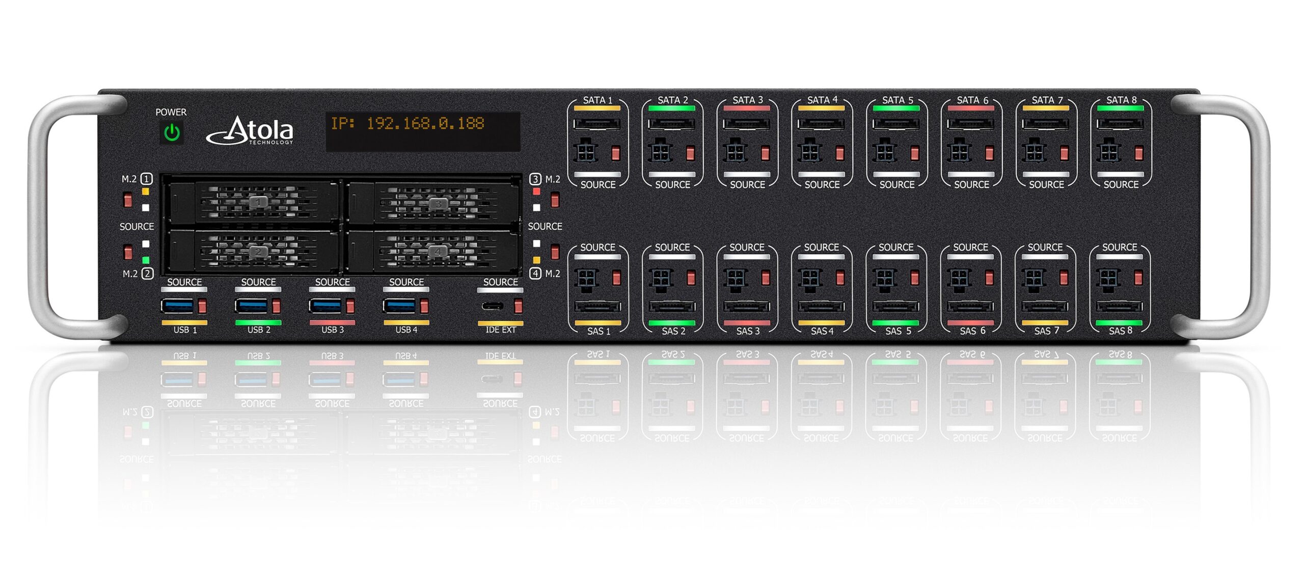
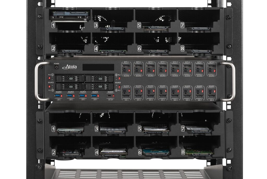
For the use on a server rack, the front panel had to be the primary location for controls and drive connections: 25 of the 26 ports including 8 SATA, 8 SAS, 4 NVMe M.2/U.2, 4 USB drives and an IDE drive via adapter are located on the front panel. In addition, there is a PCI Express port on the back side of the unit used for extensions that support M.2 SSD, Apple PCIe SSD and Thunderbolt interfaces.
We managed to fit all these ports and controls into a front panel that’s only 100mm high, which is a little less than 2.5U (U aka “rack unit” is a standard measurement unit for the height of server rack equipment and equals 1.75” or 44 mm).
Fun trivia: The first TaskForce 2 prototype was made from a cardboard box. All the ports and indicators were drawn with a felt-tip pen! We designed this prototype in a group and it was presented at Atola’s Innovation Day, an annual event where employees work in hackathon mode on new ideas.
FF: Why did you decide to add color LED indicators to the device?
TaskForce 2 introduces dual LED indicators on each port for at-a-glance feedback on system status and drive operations. The Source/Target indicator shows the port’s mode, helping to prevent accidental data overwrites and ensuring the integrity of evidence. The second indicator provides real-time feedback on the task performed on the connected hard drive.
Since the launch of its first imager in 2008, Atola has incorporated diffuse round green LEDs as a signature design element in its devices. This time, we switched to programmable RGB LEDs for more nuanced and informative indicators that enhance the communication of process status on each port.
Implementing the new RGB LEDs presented a significant engineering challenge. The LEDs’ appearance required a light pipe, and we found a transparent material with excellent light transmission capabilities that can be precisely manufactured to tolerances of 0.1 mm for a component measuring 19×2 mm.
We initially explored milling technology to create the light pipe components, but the results proved inconsistent. Then we tried out low-volume molding using silicone molds, a process that delivered high-quality parts at an acceptable cost. The outcome was remarkable: the new indicators looked fantastic, exceeding the expectations of the entire team.
Here’s a breakdown of the color scheme used for a port’s status indication:
- Green blinking: Indicates that an active process, such as imaging or another task, is in progress on the port.
- Green steady: Signals the successful completion of a task on the port.
- Yellow steady: Indicates that a task has been completed, but with some issues encountered during the process.
- Red steady: Signifies that a task on the port has failed.
This design empowers users to effortlessly monitor and assess the progress of their tasks.
Fun fact: If you’re at a forensics conference, stop by the Atola booth and ask them to turn on the police lights on the TaskForce 2. You’ll see what these LEDs are capable of.
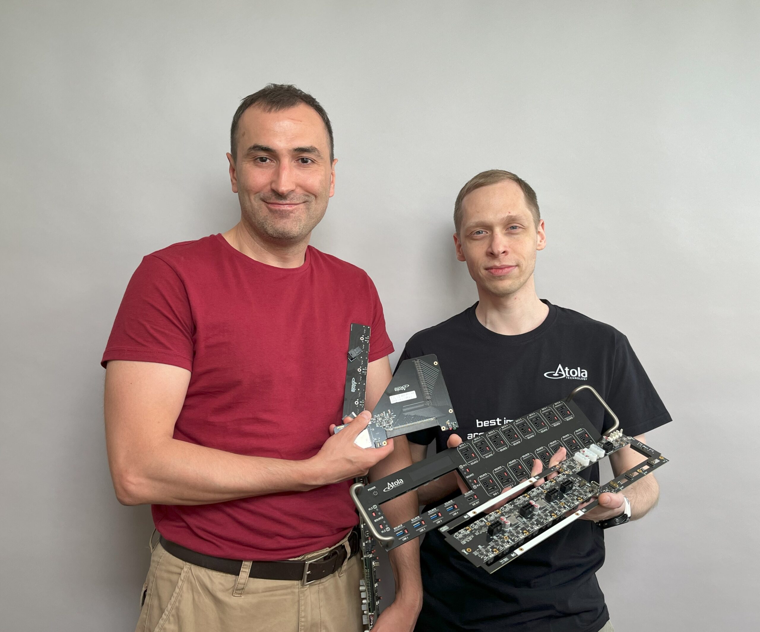
FF: The heart of every device is its motherboard. What are the other boards you included and what functions do they serve?
TaskForce 2 is based on a commercially available motherboard and relies on 7 other proprietary PCBs developed by Atola. The boards responsible for power management, status indication, and Source/Target mode control for individual SATA, SAS, USB and PCIe ports are the most important to the end user. Their core features are:
- Protection of the imager from a short circuit, generated by a connected faulty drive.
- Control of the drive power supply.
- Measurement of electric current. For SATA and SAS drives, we track the current on the 5V and 12V lines. For PCIe, the 3.3V and 12V lines. USB devices use only 5V, so we only measure the current on that line. You can find the graphs of the current consumption in the drives’ diagnostic reports.
The so-called Main PCB has additional features:
- Overcurrent protection for 4 NVMe ports rated at 5A level for 5V and 12V, without measuring current.
- Fan speed control to maintain an optimal balance of cooling and noise.
- An alphanumerical OLED display shows the unit’s IP address and other information.
Here is another fun fact: the SATA/SAS Main PCB contains only power connectors for hard drives. The eSATA connectors for data transfer tend to wear out faster than their respective power connectors, so they were placed on smaller, separate boards. It is optimized for fast, cost-effective replacement when they wear out. This way, we provided for TaskForce’s 2 efficient maintenance during its long lifecycle.
FF: How are the drives connected to the device?
It depends on the drive’s interface. If it’s a 2.5″ or 3.5″ SATA or SAS, we use a universal cable, which TaskForce 2 has inherited from our previous imagers: DiskSense 2 and TaskForce. This cable has an eSATA connector for data transfer and a Molex Microfit 4-pin for power supply. On the drive side, it has an SFF-8482 connector (also known as SAS 29-pin), which is compatible with both SAS and SATA drives.
For drive connections, Atola continues to rely on universal cables, which are more reliable than drive racks with built-in contacts. When a cable wears out, it’s easy to diagnose and replace, and the problem is limited to a single device port. If we used a drive bay, we would have to replace the entire bay, resulting in longer downtime.
To connect USB drives, we use USB 3.2 Type-A ports, and the drive is connected using its standard cable. To connect NVMe drives, we use an IcyDock, a fast, user-friendly and durable solution.
FF: Why did you opt for NVMe docks?
We looked at different ways of connecting M.2 NVMe drives. IcyDock products stood out because of their excellent design. Atola and IcyDock designs have a lot in common and both have a solid black painted metal case. The ability to easily hot-swap drives was another key benefit: you plug an M.2 drive into the connector and put it in the tray, which is then securely inserted into the IcyDock.
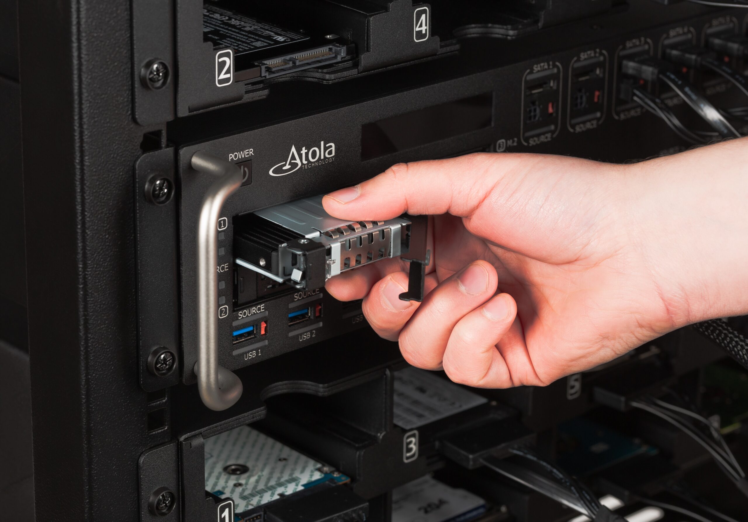
We tried out a few Icy Dock models and settled for the MB699VP model due to its user-friendly design, allowing for frequent and effortless drive swaps. It was originally designed for U.2 drives up to 15mm in height, the support of which is now a bonus feature. To connect M.2, an adapter is used: the M.2 drive sits in the dock and connects to an internal card with an M.2 connector, while externally this card has a U.2 connector that mimics the concept of SATA/SAS connectors, which were designed and tested for numerous connection cycles.
And the best thing about this solution is the speed of 4.5 GB/sec on each of the M.2 ports. You have never acquired NVMe or PCIe drives faster!
FF: Is TaskForce 2 compatible with other existing Atola extensions?
We made sure that the new unit works with all existing Atola extensions. The Atola extension port is an extended version of the PCIe interface from the motherboard, protected against ESD and excessive power consumption.
TaskForce 2 has a PCIe 4.0 x16 interface with a theoretical maximum data transfer rate of 32GB/s. The new imager’s extension interface is a big step forward in bandwidth compared to the previous Atola products, which had a PCIe 3.0 x8 interface.
FF: How did you get the idea for the device rack?
Compact drive placement in the forensic workplace has been one of the most requested features since 2018. When designing TaskForce 2 in 2021, we realized the new unit would require a dedicated drive organization system.
The core of the drive organization system is a case that is installed in a 19″ rack right next to TaskForce 2, within reach of our standard drive cables. This design must be compatible with all possible 3.5″ and 2.5″ disk form factors, and all possible drive height variations, from 7mm to 15mm for some server SAS models.
We were looking for a simple and reliable solution, inspired by an idea I came across a long time ago in a science fiction novel by British author Arthur C. Clarke: “No machine may contain any moving parts”. It is a utopian ideal, almost unattainable in reality. It implies that the fewer parts there are in a device, the better: fewer parts mean fewer potential points of failure and lower production and assembly costs.
For our project, this idea meant minimizing the number of moving parts, ideally to zero. At the same time, the rack had to ensure a fast and effortless drive swap. The task was complicated by the fact that each cell of the rack had to fit all known form factors:
- SATA/SAS desktop drives of 102 x 147 mm, up to 26mm high
- Mobile SATA drives of 70 x 100 mm, 7mm or 9.5mm high
- Mobile SAS drives of 70 x 100 mm, up to 15 mm high
We have looked at different design options and settled for the most suitable concept: A simple shelf is divided into disk cells, in which you can place a drive horizontally, secured with corners preventing the drives from slipping out if you accidentally pull a cable.
As straightforward as the design may sound, its practical implementation was much trickier.
Four drives take up almost the entire width of a 19″ rack. We still had to fit the case and cell walls. The hardware engineers had to really “rack their heads” but we did tackle all the challenges and designed a rack that holds 8 drives and has a fan to keep them cool. A rack can be installed in a 19-inch rack or sit on a desk; it can be placed above or under TaskForce 2. Optimally, a rack above TaskForce 2 is used for all the drives plugged into SATA ports and another one is underneath to accommodate the drives in SAS ports.
The racks brought a substantial improvement to the user experience, and we could not be happier with the outcome.
FF: What’s next for Atola in terms of hardware design?
We are busy developing a brand new standalone imager. With a comprehensive range of ports and market-unique features, it will be crafted to handle the most complex tasks with ease. While I can’t reveal too much yet, this imager is set to redefine your workflow and elevate your forensic toolkit.
Stay tuned for more sneak peeks and behind-the-scenes updates by following Atola on LinkedIn!